
-

Schematic diagram of photovoltaic panel installation principle
This is the detailed solar panel connection diagram that shows how the system is actually wired, including conductor routing, terminations, and install-level details the crew needs to build it correctly. You'll be ready to power up your home or get on the road in no time. What Is a Solar Panel Wiring Diagram? A solar panel wiring. . This article explains these diagrams and how to use them for successful solar operations. Find out everything you need to produce these important design elements without encountering any drawbacks Creating the photovoltaic system diagram represents an important phase in. . Have you decided to install your own photovoltaic system but don't know where to start? We have produced a number of connection diagrams for the various components of a solar photovoltaic system.
[PDF Version]
-
Photovoltaic bracket symbol diagram
A free online tool to easily create, customize, and export professional solar power system diagrams. Drag and drop components, connect lines, and save your work. . The photovoltaic system diagram is the fundamental design asset for installing an efficient solar energy system. . Discover a comprehensive guide to understanding the symbols behind solar PV systems and their components Today we're going to explore the fascinating world of one-line diagram symbols used in photovoltaic (PV) system design.
[PDF Version]
-

Solar inverter line group structure diagram
A free online tool to easily create, customize, and export professional solar power system diagrams. Drag and drop components, connect lines, and save your work. . © 2025 - 2026 Solar Diagram Tool. . AC disconnect located next to inverter if inverter is not next to 40A AC breaker. Otherwise, disconnect is not required (per the NEC, but may be required per the utility). Note: this wiring diagram is simply an example. 3-wire NM cable ran through attic. 3⁄4 EMT. . Unlock the secrets of solar one-line diagrams! Discover a comprehensive guide to understanding the symbols behind solar PV systems and their components Today we're going to explore the fascinating world of one-line diagram symbols used in photovoltaic (PV) system design. Please be aware that the various appliances or electronics in. . Electrical Line Diagrams are schematic representations that illustrate how electrical components in a solar PV system are interconnected.
[PDF Version]
-

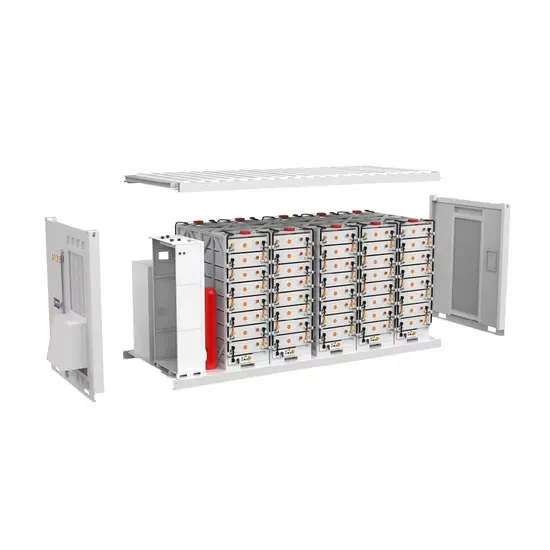
Photovoltaic energy storage battery shell structure diagram
In these cases, using a photovoltaic system design software will allow you to size and configure the storage system by defining the type of battery and meter. The image represents a diagram for the production of electricity generated from a photovoltaic system. It's more than just a drawing; it is a detailed plan that illustrates how every component connects and interacts to generate, store, and deliver power. For homeowners, installers, and DIY. . Summary: This article explores innovative design strategies for energy storage battery enclosures, analyzing material selection, thermal management, and structural integrity. DC-DC converter and solar are connected on common DC bus on the PCS. . Photovoltaic Plant and Battery Energy Storage System Integration at NREL's Flatirons Campus NREL is a national laboratory of the U. Primary Role: Cells are the core power source.
[PDF Version]